Project Detail
Nearly half of the American population lives within 50 miles of coastlines. In 2014, the U.S. Department of Energy (DOE) Wind Program selected three (3) projects to advance to the second phase of demonstration, which included follow-on design, fabrication, and deployment in order to achieve commercial operation by 2017.
Ocean Power Technologies (OPT), based in New Jersey, advanced one of those projects receiving Energy Department support to develop its PB150B2 wave conversion unit that captures energy by moving up and down as waves pass. The proposed grid would generate 1.5-megawatts of energy – about half that of a single giant wind turbine – and be the first commercial-scale wave energy project in the U.S.
The Unit #1 project was for the first of 3 of 10 planned wave PowerBuoys for that site. The Unit consisted of two (2) major subsystems; 1) the PowerBuoy and 2) the Anchor and Mooring System. The anchor and mooring system consisted of three (3) Floating Gravity Base Anchors (FGBA) constructed of reinforced concrete, cylindrical in shape. Each anchor measured approximately 33-ft in dia. x 25-ft in height with 22-ft draft and an engineered weight of 550-tons in the dry and 300-tons when submerged. Each anchor had three (3) internal vertical chambers, designed with air and water flooding systems to enable full submersion and recovery. The Project was planned in key phases: Trials Phase; Mooring and Anchoring System Deployment; and PowerBuoy Installation.
Floating Gravity Base Anchor Ballasting (FGBA) Trial
Prior to final deployment, a trial run of the ballasting and de-ballasting of the FGBA process was required to provide an in-depth understanding of the deployment of the process for ballasting and de-ballasting the FGBA. A single FGBA anchor assembly was tested at the upper turning basin in Coos Bay with a depth of approximately 50-ft. The FGBA was deployed by flooding a central trim ballast tank built into the structure giving the FGBA approximately 5.5-tons negative buoyancy. The assembly was then lowered to the sea bed using a controlled descent from the support vessel using the engineered winch system. Once the unit reached the bottom, the remainder of ballast tanks were flooded to achieve full ballast weight. The process was then reversed and the unit recovered for deployment.
Mooring and Anchoring System Deployment
The first of the site operations was the Mooring and Anchoring deployment. PPM departed Jordan Cove to deploy first FGBA. The deployment barge was positioned over the installation site and secured using 4-point anchor system. The first of 3 FGBAs were transited in open water to the deployment site undertow, secured to the deployment lines, and then moved into position between the engineered deployment frame off the barge in preparation to be lowered to the seabed by a controlled decent. Chamber volumes were engaged to create a slight negative buoyancy during decent assisted by deployment lines terminated with a 2.5-in dia. the braided poly line to assist with dynamic loading. Tendon line 80-mm in dia. at 35-m in length were attached to each clevis. Opposite end tendon line was attached to the lower end of Auxiliary Subsurface Buoy (ASB); an air and water floodable tank designed to tension the final mooring spread. Each ASB was 12.5-ft in dia. x 25-ft in length with an engineered weight of 12 -tons in the dry and net buoyancy of 40-tons when submerged. The FGBA and corresponding ASB were designed to be deployed as a unit with a design depth of 180- to 230-ft below the surface.
PowerBuoy Installation
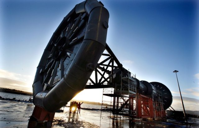
The Power Buoy PB150B2 unit was initially fabricated in Vancouver, WA, and transferred to Vigor Marine in Portland, OR for completion and relocated to a staging site in Coos Bay in preparation for ultimate deployment. OPT contracted with Oregon Iron Works to complete the buoys. The first buoy measured 150-ft tall by 40-ft wide weighing 200-tons. Once the anchoring system was installed, it was anticipated the PowerBuoy structure would be prepared and pre-rigged with all upper bridles, lower bridles, tri-plates, and inner mooring lines. The PowerBuoy would then be towed from the staging area to the final site in a horizontal position using an appropriately sized ocean tug.
OPT used a precautionary approach to project development, including provisions for adaptive management and scientific monitoring of ecological and socioeconomic effects. The Unit#1 Mooring and Buoy Installation project was a component of the larger project to install as many as 100 units, pending additional permits, approximately 2 1/2 miles off the central coast of Reedsport, OR. The project was canceled before Unit#1 could be completed to focus on another project in Australia. OPT and the DOE agreed in principle to proceed with a termination mutually agreeing to cover the ocean deployment of the single PowerBuoy.